Alternating Current-Test Papers
CBSE Test Paper-01
Class - 12 Physics (Alternating Current)
- A 200 ohm resistor is connected in series with a capacitor. The voltage across the resistor is VR = (1.20 V) cos(2500 rad/s)t.Capacitive reactance is
- 70
- 80
- 60
- 90
- The current in a series LCR circuit will be maximum, then is:
- as large as possible
- equal to natural frequency of LCR system
- A series circuit consists of an ac source of variable frequency, a 115.0 resistor, a 1.25 capacitor, and a 4.50-mH inductor. Impedance of this circuit when the angular frequency of the ac source is adjusted to twice the resonant angular frequency is
- 146.0
- 176.0
- 166.0
- 156.0
- For high frequency capacitor offers:
- Less resistance
- More resistance
- None of these
- Zero resistance
- Effective voltage Vrms is related to peak voltage Vo by
- Vrms = 0.707 Vo
- Vrms = 0.787Vo
- Vrms = 0.9 Vo
- Vrms = 0.5 Vo
- An AC current, I = I0 sin produces certain heat H in a resistor R over a time . Write the value of the DC current that would produce the same heat in the same resistor in the same time.
Define the term rms value of the current. How is it related to the peak value?
Define the term wattless current.
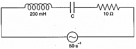
The figure shows a series L-C-R circuit connected to a variable frequency 250 V source with L = 50 mH, C = 80F and R = 40 .
- the source frequency which drives the circuit in resonance.
- the quality factor (Q) of the circuit.
The number of turns in secondary coil of a transformer is 100 times the number of turns in the primary coil. What is the transformation ratio?
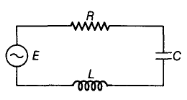
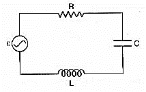
In the following circuit, calculate,
- the capacitance 'c' of the capacitor if the power factor of the circuit is unity, and
- also calculate the Q-factor of the circuit.
A source of AC voltage V = V0 sin is connected to a series combination of a resistor 'R' and a capacitor 'C'. Draw the phasor diagram and use it to obtain the expression for
- impedance of the circuit and
- phase angle.
- For a given AC, i = im sin , show that the average power dissipated in a resistor R over a complete cycle is .
- A light bulb is rated at 100 W for a 220V AC supply. Calculate the resistance of the bulb.
An LC circuit contains a 20 mH inductor and a capacitor with an initial charge of 10 mC. The resistance of the circuit is negligible. Let the instant the circuit is closed be t = 0.
- What is the total energy stored initially? Is it conserved during LC oscillations?
- What is the natural frequency of the circuit?
- At what time is the energy stored
- completely electrical (i.e. stored in the capacitor)?
- completely magnetic (i.e. stored in the inductor)?
- At what times is the total energy shared equally between the inductor and the capacitor?
- If a resistor is inserted in the circuit, how much energy is eventually dissipated as heat?
A series of LCR circuit connected to a variable frequency 230 V source, L = 5.0 H, ,
- Determine the source frequency which drives the circuit in resonance.
- Obtain the impedance of the circuit and the amplitude of current at the resonating frequency.
- Determine the rms potential drops across the three elements of the circuit. Show that the potential drop across the LC combination is zero at the resonating frequency.
CBSE Test Paper-01
Class - 12 Physics (Alternating Current)
Answers
- 80
Explanation: VR = (1.20 V) cos(2500 rad/s)t
Capacitive reactance
- 80
- equal to natural frequency of LCR system
Explanation: for maximum current in LCR series circuit impedance Z will be minimum
impedance Z will be minimum when
hence
this is equal to natural frequency of LCR system
- equal to natural frequency of LCR system
- 146.0
Explanation:
resonant angular frequency
given that the angular frequency of the ac source
impedance
- 146.0
- Less resistance
Explanation: capacitive reactance
hence, for high frequency capacitor offers less resistance.
- Less resistance
- Vrms = 0.707 Vo
Explanation: Average value of V2 over a complete cycle is given by
The root-mean-square value of the alternating voltage is given by
Vrms = 0.707 V0
- Vrms = 0.707 Vo
Heat produced by DC is H = I2RT ....(i)
Heat produced by AC is
....(ii)Where IV = I0/ = rms value of the AC current
From Eqs. (i) and (ii), we get
where I stands for DC and I0 is the peak value of AC current.It is defined as the value of Alternating Current (AC) over a complete cycle which would generate same amount of heat in a given resistor that is generated by steady current in the same resistor and in the same time during a complete cycle. It is also called virtual value or effective value of AC.
Let the peak value of the current be I0
Where, I0 peak value of AC.The current in an AC circuit is said to be Wattless Current when the average power consumed in such circuit corresponds to Zero.Such current is also called as Idle Current.
Given, L = 50mH =
- In the L-C-R, the resonant angular frequency when XL= XC
- Quality factor,
- In the L-C-R, the resonant angular frequency when XL= XC
Transformation ratio
Since
Thus- Power factor, or Z = R [For power factor unity ]
or
or
or - Q-factor
- Power factor, or Z = R [For power factor unity ]
From diagram, by parallelogram law of vector addition, VR + VC = V
Using pythagorean theorem,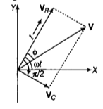
We get
, XC and R being the capacitive reactance and resistance of the resistor respectively.
(say) where, Z =
Z = impedance of the circuit.- The phase angle between resultant voltage and current is given by
tan-1()
- The average power dissipated,
- ) Power of the bulb P = 100 W
voltage, V = 220 V
- The average power dissipated,
- Total initial energy
= 1 J
This energy shall remain conserved in the absence of resistance. - Angular frequency,
= 103 rads-1
Or , where = 6.3 ms
Energy stored is completely electrical at t = 0, T/2, 3T/2 . . .
Electrical energy is zero i.e. energy stored is completely magnetic at- At
Electrical energy , which is half of the total energy. - R damps out the LC oscillations eventually. The whole of the initial energy 1.0 J is eventually dissipated as heat.
- Total initial energy
Here, L = 5.0 H,
Ev = 230 volt- Resonance angular frequency,
= 50 rad/sec = 50 rad/sec. - Impedance
At resonance,
Amplitude of current at resonating frequency
= 8.13 amp - Potential drop across L
= 1437.5 V
Potential drop across R
= 230 volt
Potential drop across C
= 1437.5 V
Potential drop across LC circuit
- Resonance angular frequency,