Wave Optics-Revision Notes
CBSE Class 12 Physics
Revision Notes
Chapter-10
Wave Optics
- Wave front: It is the continuous locus of all such particles of the medium which are vibrating in the same phase of oscillation at any instant.
Depending upon the shape of the source of light, the wavefront is of different shapes:
(i) Plane wavefront
(ii) Spherical wavefront
(iii) Cylindrical wavefront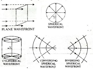
- Rays: Rays are the arrows perpendicular to the wavefront in the direction of the propagation of a wave.
- Time Taken: The time taken for light to travel from one wavefront to another is called time taken by a ray.
- Huygen's Principle:
- According to Huygen's 'each point on the given wavefront (called primary wavefront) acts as a fresh source of new disturbance, called secondary wavelet, which travels in all directions with the velocity of light in the given medium'.
- A surface touching these secondary wavelets, tangentially in the forward direction at any instant gives the new wavefront at that instant. This is called secondary wavelets.
- Principle of Huygen's Construction:
- It is based on the principle that every point on a wavefront is a source of a secondary wavefront.
- The envelope of these wavefronts i.e., the surface tangent to all the secondary wavefront gives the new wavefront.
- Snell’s law of refraction:
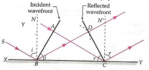
- Reflection of Plane Waves Using Huygen's Principle: The law of reflection (i = r) can be derived using the wave theory.
Refraction of Plane Waves Using Huygen's Principle: the Snell’s law of refraction can be derived using the wave theory. (Here v1 and v2 are the speed of light in media 1 and 2 with refractive index and respectively).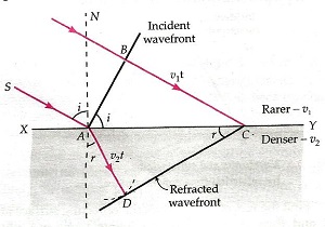
- Relation between Frequency and Speed: The frequency remains the same as light travels from one medium to another. The speed v of a wave is given by
where is the wavelength of the wave and is the period of oscillation. - Doppler Effect: Whenever there is a relative motion between the source and observer then the apparent frequency of light received by the observer is different from the actual frequency emitted by the source of light. This effect is called Doppler's effect in the light. The effect can be used to measure the speed of an approaching or receding object.
- Change in Frequency: The fractional change in frequency or Doppler shift is given by
where vradial is the component of the source velocity along the line joining the observer to the source relative to the observer. vradial is taken positive when the source moves away from the observer. - Coherent sources:- Two sources of light that continuously emit light waves of the same frequency (or wavelength) with a zero or constant phase difference between them are called coherent sources.
- Incoherent sources:- Two sources of light which do not emit light waves with a constant phase difference are called incoherent sources.
- According to the superposition principle when two or more wave motions traveling through a medium superimpose one another, a new wave is formed in which resultant displacements due to the individual waves at that instant is given by-
- The total intensity I is not just the sum of individual intensities I1 and I2 due to the two sources but includes an interference term also as-
where is the inherent phase difference between the two superimposing waves.
- The interference term averaged over many cycles is zero if
- The sources have different frequencies or
- The sources have the same frequency but no stable phase difference.
- For such coherent sources -
The resultant intensity depends on the relative location of the point from the two sources, since changing it changes the path difference as we go from one point to another.
- As a result, the resulting intensity will vary between maximum and minimum values, determined by the maximum and minimum values of the cosine function. These will be
=
=
where a1 and a2 are amplitudes of waves.
- Young’s Experiment:
Two parallel and very close slits S1 and S2 (illuminated by another narrow slit) behave like two coherent sources and produce a pattern of dark and bright bands on a screen known as interference fringes.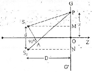
For a point P on the screen, the path difference
Where d is the separation between two slits, D is the distance between the slits and the screen and x is the distance of the point of P from the central fringe.
For constructive interference (bright band), the path difference must be an integer multiple of , i.e.-
The separation between adjacent bright (or dark) fringes called fringe width is given by,
using which can be measured. - Constructive Interference:
- Phase difference : where n is an integer
- Path difference: where n is an integer
- Destructive interference:
- Phase difference : , where n is an integer
- Path difference: , where n is an integer
- Intensity distribution curve for interference:
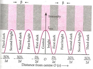
- Interference fringes with white light:- When the slits are illuminated with white light, the interference pattern consists of a central white fringe having on both sides a few coloured fringes and then a general illumination.
Conditions for sustained interference:-
(i) Two sources of light must be coherent.
(ii) The frequencies (or wavelength) of the two waves should be equal.
(iii) The light must be monochromatic.
(iv) The amplitudes of the interfering waves must be equal or nearly equal.
(v) The two sources must be narrow. - Diffraction: The phenomenon of bending of light around the corners of an obstacle is called the diffraction of light.
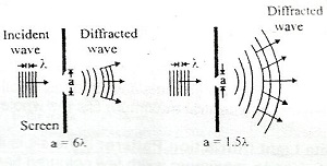
- Diffraction due to Single Slit:
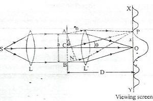
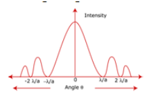
- The single-slit diffraction pattern shows the central maximum at = 0 and other secondary maxima at = (n + ) , and has minima (zero intensity) at = where n = ±1, ±2, ±3..
- Angular spread of the central maxima
- Linear Width of the central maxima =
Where D is the distance of the slit from the screen, a is the slit width.
- Condition for the Minima on either side of the Central Maxima: , where n = 1,2,3,….
- Relation between phase difference & path difference:
Where is the phase difference & is the path difference. - Different Parts of the WaveFront at the Slit act as Secondary Sources:
- The diffraction pattern is the result of the interference of waves from these sources.
- The intensity plot shows below a bright central maximum, followed by smaller intensity secondary maxima, with there being points of zero intensity in between, whenever
- The width of the central maximum is directly proportional to the wavelength of light and inversely proportional to the width of the slit.
- Emission, Absorption, and Scattering:
- These are the three processes by which matter interacts with radiation. In emission, an accelerated charge radiates and loses energy.
- In absorption, the charge gains energy at the expense of the electromagnetic wave.
- In scattering, the charge accelerated by incident electromagnetic wave radiates in all directions.
- Resolving Power of Optical Instrument: It is the ability of the instrument to produce distinctly separate images of two close objects.
- Resolving Power of Microscope =
where dmin is the minimum separation of two points, is the half-angle of the cone of light from the point object. The product is called the numerical aperture. - Polarization:
- If the vibrations of a wave are present in just one direction in a plane perpendicular to the direction of propagation, the wave is said to be polarised or plane polarised. The phenomenon of restricting the oscillations of a wave to just one direction in the transverse plane is called polarisation of waves.
- When light passes through a single polaroid P1 light intensity is reduced to half, independent of the orientation of P1. When a second Polaroid P2 is also included, at one specific orientation w.r.t P1, the net transmitted intensity is reduced to zero but is transmitted fully when P1 is turned 900 from that orientation.
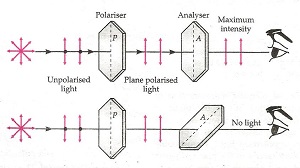
- Polariser: A device that polarises the unpolarised light passed through it is called a polariser.
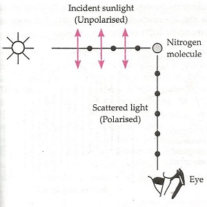
- Unpolarized sunlight scattered by the atmosphere or reflected from a medium gets partially polarized.
- Optical Activity: When plane polarised light passes through a certain substance, the plane of polarization of the light is rotated about the direction of the propagation of light through a certain angle. This phenomenon is called optical activity or optical rotation and the substances optically active.
- Intensity of the Light due to Polarization (Law of Malus):
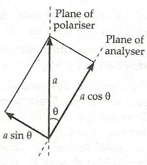
Where I is the intensity of light after polarization, Io is the original intensity, is the angle between the axis of the analyzer & the polarizer
A graph between the intensity of light I transmitted by the analyzer and the angle between the polarizer and the analyzer will be as shown-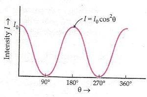
- Methods of producing plane-polarized light:
- Reflection
- Scattering
- Double refraction
- Polarisation by Reflection (Brewster’s Law): When unpolarized light is incident on a transparent surface at the polarizing angle ip or iB, the reflected light is polarised with its electric vector perpendicular to the plane of incidence when the refracted and reflected rays make a right angle with each other, i.e.
where iB = Brewster's angle and = refractive index.
iB + rp = 90o , i.e. reflected plane-polarized light is at right angle from refracted light.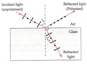
- Polarization by Scattering:
- Light is scattered when it meets a particle of similar size to its own wavelength. The scattering of sunlight by dust particles is an example of polarization by scattering.
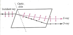
- Polarization by Double Refraction: When an unpolarised ray passes through certain crystals like quartz or calcite, it splits up into two rays. This phenomenon is called double refraction.
- Rayleigh showed that the scattering of light is proportional to the fourth power of the frequency of the light or varies as where is the wavelength of light incident on the air molecules of size ‘d’ where . Hence blue light is scattered more than red. This explains the blue colour of the sky.
- Polaroids: Polaroids are thin commercial sheets that make use of the property of selective absorption to produce an intense beam of plane polarised light.
- Uses of polaroids- In sunglasses and camera filters, in wind screens, in window panes of airplanes, in LCDs etc.