Alternating Current-Revision Notes
CBSE Class 12 Physics
Revision Notes
Chapter-7
Alternating Current
- Alternating Current: The current whose magnitude changes with time and direction reverses periodically is called alternating current. Alternating emf E and current I at any time are given by:
where,
where,
where, T is the time period.
- Values of Alternating Current and Voltage:
- Instantaneous value: It is the value of alternating current and voltage at an instant t.
- Peak value: Maximum values of voltage e0 and current I0 in a cycle are called peak values.
- Mean or average value of a.c.: It is defined as the value of AC which would send the same charge in a circuit at the same time as is sent by the steady current in its half time period. For complete cycle, the mean value of AC will be zero.
Mean value for half cycle:
- Root – mean- square (rms) or effective or virtual value of a.c.: It is defined as that value of AC which produces the same heating effect in a given resistor that is generated by steady current in the same resistor and in the same time during a complete cycle.
RMS values are also called apparent or effective values.
- Phase difference Between the EMF (Voltage) and the Current in an AC Circuit: A diagram that represents alternating current and voltage of the same frequency as rotating vectors (phasors) alongwith proper phase angle between them is called a phasor diagram.
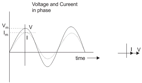
- For pure resistor: The voltage and the current are in the same phase i.e. phase difference,
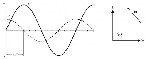
- For pure inductor: The voltage is ahead of current by i.e. phase difference,

- For pure capacitor: The voltage lags behind the current by i.e. phase difference
- Reactance: The non-resistive opposition to the flow of a.c. is called reactance.
- ,
- ,
- Impedance: It is defined as the effective resistance of the series LCR-circuit which opposes the flow of current through it is called impedance.
- For L – R series circuit:
- For R – C series circuit:
or
- For L – C series circuit:
Or
- Conductance: Reciprocal of resistance is called conductance. Its unit is mho. It is given as,
{tex}G=\frac{1}{R}\{/tex}
- Power in an ac circuit:
- Electric power = (current in circuit) x (voltage in circuit)
P = IE
- Instantaneous power:
- Average power:
- Virtual power (apparent power):
- Power Factor: It is defined as the ratio of the true power to the apparent power of an a.c. circuit.
- For purely resistive circuit-
- For purely inductive or capacitive circuit-
- For LCR circuit-
- Wattless Current: The component of current differing in phase by relative to the voltage, is called wattless current.
- The rms value of wattless current:
The component is called wattless current because it does not consume any power in a.c. circuit.
- Choke Coil:
- An inductive coil used for controlling alternating current whose self- inductance is high and resistance negligible, is called choke coil.
- The power factor of this coil is approximately zero.
- It controls current without consuming any power.
- Series Resonant Circuit
- When the inductive reactance (XL) becomes equal to the capacitive reactance (XC) in the circuit, the total impedance becomes purely resistive (Z = R).
- In this state, the voltage and current are in same phase ( = 0), the current and power are maximum and impedance is minimum. This state is called resonance.
- At resonance,
Hence, the resonance frequency is,
- In resonance, the power factor of the circuit is one.
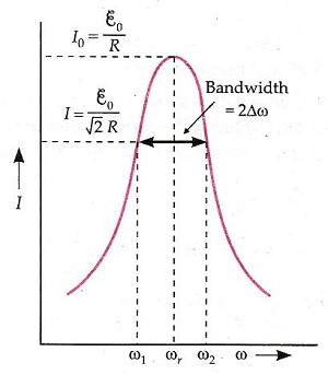
- Half – Power Frequencies: Those frequencies f1 and f2 at which the power is half of the maximum power (power at resonance).
- Band – Width: It is the range of frequencies over which at least half of the maximum power and current is provided.
- The frequency interval between half-power frequencies is called bandwidth.
- For a series LCR resonant circuit,
- Quality Factor (Q): It is defined as the ratio of the resonant frequency to the difference in two frequencies taken on both sides of the resonant frequency such that at each frequency, the current amplitude becomes times the value at resonant frequency.
- LC-Oscillations:- When a charged capacitor is allowed to discharge through a non-resistive inductor, electrical oscillations of constant amplitude and frequency are produced. These oscillations are called LC-oscillations.
- Transformer:- It is an electrical device for converting an alternating current at low voltage into that at high voltage or vice versa.
- If transformer increases the input voltage, it is called step-up transformer.
- If transformer decreases the input voltage, it is called step-down transformer.
- It works on the principle of mutual induction, i.e. when a changing current is passed through one of the two inductively coupled coils, an induced emf is set up in the other coil.
- Energy losses in transformers-
- Copper losses
- Eddy current losses
- Hysteresis loss
- Flux leakage
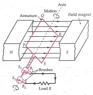
- A.C. Generator:- It is a device which converts mechanical energy into electrical energy.
- Principle: It is based on the principle of electromagnetic induction.