Electrostatic Potential and Capacitance-Solutions
CBSE Class 12 Physics
NCERT Solutions
Chapter - 2
Electrostatic Potential and Capacitance
1: Two charges and are located 16 cm apart. At what point(s) on the line joining the two charges is the electric potential zero? Take the potential at infinity to be zero.
Ans: There are two charges,
Distance between the two charges, d = 16 cm = 0.16 m
Consider a point P between the two charges,on the line joining the two charges, as shown in the given figure.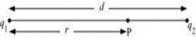
r = Distance of point P from charge q1
Let the electric potential (V) at point P be zero.
Potential at point P is the sum of potentials due to the fields of charges q1 and q2 respectively.
........(i)
Where,
= Permittivity of free space
For V = 0, equation (i) reduces to
Therefore, the the potential is zero at a point located between the two charges at a distance of 10 cm from the positive charge .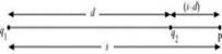
Let point P, where potential is zero, be outside the system of two charges at a distance s from the positive charge, as shown in the following figure.
For this arrangement, potential is given by,
...... (ii)
For V = 0, equation (ii) reduces to
Therefore, the potential is zero at a distance of 40 cm from the positive charge outside the system of charges.
2. A regular hexagon of side 10 cm has a charge 5 at each of its vertices. Calculate the potential at the centre of the hexagon.
Ans. The given figure shows six equal amount of charges, q, at the vertices of a regular hexagon.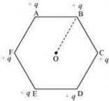
Where,
Charge,
Side of the hexagon, d = AB = BC = CD = DE = EF = FA = 10 cm
For a regular hexagon, the distance of each vertex from center O, d = 10 cm
Electric potential at point O,
Where,
= Permittivity of free space
Therefore, the potential at the centre of the hexagon is .
3: Two charges and are placed at points A and B 6 cm apart.
- Identify an equipotential surface of the system.
- What is the direction of the electric field at every point on this surface?
Ans: The situation is represented in the given figure.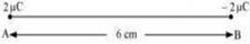
- A surface at which potentially remains same at each point is known as equipotential surface. The equipotential surface selected may be a plane located at the midpoint of AB and normal to line joining the charges. On this plane, the potential is zero since all points on the plane are equidistant from the two charges.
- The direction of the electric field at every point on this surface is normal to the plane in the direction of AB.
4: A spherical conductor of radius 12 cm has a charge of distributed uniformly on its surface. What is the electric field
- Inside the sphere
- Just outside the sphere
- At a point 18 cm from the centre of the sphere?
Ans: Radius of the spherical conductor, r = 12 cm = 0.12 m
Charge q is uniformly distributed over the conductor,
- Electric field inside a spherical metallic conductor is zero. The charge inside the sphere is zero and all the charge resides on the surface of the charged conductor.
- Electric field E just outside the conductor is given by the relation,
Where, and = Permittivity of free space
= 105 NC-1
Therefore, the electric field just outside the sphere is 105 NC-1. - Electric field at a point 18 m from the centre of the sphere = E1
Distance of the point from the centre, d = 18 cm = 0.18 m
Therefore, the electric field at a point 18 cm from the centre of the sphere is .
5: A parallel plate capacitor with air between the plates has a capacitance of 8 pF . What will be the capacitance if the distance between the plates is reduced by half, and the space between them is filled with a substance of dielectric constant 6?
Ans: Capacitance between the parallel plates of the capacitor, C = 8 pF
Initially, distance between the parallel plates was d and it was filled with air. Dielectric constant of air, k = 1
Capacitance, C, is given by the formula,
Where,
A = Area of each plate
= Permittivity of free space
If distance between the plates is reduced to half, then new distance,
Dielectric constant of the substance filled in between the plates, k = 6
Hence, capacitance of the capacitor becomes
(Since k =6)
Therefore, the capacitance between the plates is 96 pF.
6: Three capacitors each of capacitance 9 pF are connected in series.
- What is the total capacitance of the combination?
- What is the potential difference across each capacitor if the combination is connected to a 120 V supply?
Ans:
- Capacitance of each of the three capacitors, C = 9 pF
Equivalent capacitance ( C') of the series combination of the capacitors is given by the relation,
Therefore, total capacitance of the combination is . - Supply voltage, V = 100 V
Potential difference ( V) across each capacitor is equal to one-third of the supply voltage.
Therefore, the potential difference across each capacitor is 40 V.
7: Three capacitors of capacitances 2 pF, 3 pF and 4 pF are connected in parallel.
- What is the total capacitance of the combination?
- Determine the charge on each capacitor if the combination is connected to a 100 V supply.
Ans:
- Capacitances of the given capacitors a
C1 = 2pF, C2 = 3pF, C3 = 4pF
For the parallel combination of the capacitors, equivalent capacitor C is given by the algebraic sum,
C = C1 + C2 + C3
C = 2 + 3 + 4 = 9pF
Therefore, total capacitance of the combination is 9 pF. - Supply voltage, V = 100 V
The voltage across all the three capacitors is same = V = 100 V
Charge on a capacitor of capacitance C and potential difference V is given by the relation,
q = CV
For C1 = 2 pF,
For C2 = 3 pF,
For C3 = 4 pF,
8: In a parallel plate capacitor with air between the plates, each plate has an area of and the distance between the plates is 3 mm. Calculate the capacitance of the capacitor. If this capacitor is connected to a 100 V supply, what is the charge on each plate of the capacitor?
Ans: Area of each plate of the parallel plate capacitor,
Distance between the plates, d = 3 mm
Supply voltage, V = 100 V
Capacitance C of a parallel plate capacitor is given by,
Where,
= Permittivity of free space
= 17.71pF
Potential V is related with the charge q and capacitance C as
q = V C
Therefore, capacitance of the capacitor is 17.71pF and
the charge on each plate is .
9: Explain what would happen if in the capacitor given in Exercise 2.8, a 3 mm thick mica sheet (of dielectric constant = 6) were inserted between the plates,
- While the voltage supply remained connected.
- After the supply was disconnected.
Ans: Dielectric constant of the mica sheet, k = 6
- Initial capacitance,
New capacitance,
Supply voltage, V = 100 V
When the voltage supply remains connected and a dielectric is inserted between the plates of the capacitor, the potential difference across the plates remains constant and additional charge flows from the supply on to the plates so as to increase the capacitance.
New charge
Potential across the plates remains 100 V. - Dielectric constant, k = 6
Initial capacitance,
New capacitance
If supply voltage is removed, and the dielectric is introduced, the capacitance of the capacitor increases,the charge on the plates remains constant, while the potential difference across the plates falls.
Charge
Potential across the plates is given by,
= 16.7 V
10: A 12 pF capacitor is connected to a 50V battery. How much electrostatic energy is stored in the capacitor?
Ans: Capacitance of the capacitor C = 12pF,
Potential difference, V = 50 V
Electrostatic energy stored in the capacitor is given by the relation,
Therefore, the electrostatic energy stored in the capacitor is .
11. A 600 pF capacitor is charged by a 200 V supply. It is then disconnected from the supply and is connected to another uncharged 600 pF capacitor. How much electrostatic energy is lost in the process?
Ans: Capacitance of the capacitor, C = 600 pF ;Potential difference, V = 200 V
Electrostatic energy stored in the capacitor is given by,
The charge Q on the capacitor is given by,
If supply is disconnected from the capacitor and another capacitor of capacitance C = 600 pF is connected to it, the charge Q on C1 is shared between the two capacitors. The equivalent capacitance C' of the combination is given by,
C' = C1 + C2 = 600 + 600 = 1200 pF
The new potential V' across the capacitors is given by,
New electrostatic energy can be calculated as
Loss in electrostatic energy =U - U'
Therefore, the electrostatic energy lost in the process is .
12: A charge of 8 mC is located at the origin. Calculate the work done in taking a small charge of from a point P (0, 0, 3 cm) to a point Q (0, 4 cm, 0), via a point R (0, 6 cm, 9 cm).
Ans: Charge located at the origin, q = 8 mC
Magnitude of a small charge, which is taken from a point P to point R to point Q, q1 =
All the points are represented in the given figure.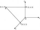
Point P is at a distance, d1 = 3 cm, from the origin along z-axis. Point Q is at a distance, d2 = 4 cm, from the origin along y-axis.
Potential at point P,
Potential at point Q,
Work done (W) by the electrostatic force is independent of the path.
..........(i)
where,
= 1.27J
Therefore, work done during the process is 1.27 J.
13: A cube of side b has a charge q at each of its vertices. Determine the potential and electric field due to this charge array at the centre of the cube.
Ans: Length of the side of a cube = b
Charge at each of its vertices = q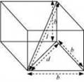
A cube of side b is shown in the following figure.
d = Diagonal of one of the six faces of the cube
l = Length of the diagonal of the cube
Is the difference between the centre of the cube and one of the eight vertices
The electric potential (V) at the centre of the cube is due to the presence of eight charges at the vertices.
Therefore, the potential at the centre of the cube is
The electric field at the centre of the cube, due to the eight charges, gets cancelled. This is because the charges are distributed symmetrically with respect to the centre of the cube. Hence, the electric field is zero at the centre.
14: Two tiny spheres carrying charges are located 30 cm apart. Find the potential and electric field:
- at the mid-point of the line joining the two charges, and
- at a point 10 cm from this midpoint in a plane normal to the line and passing through the mid-point.
Ans: Two charges placed at points A and B are represented in the given figure. O is the mid- point of the line joining the two charges.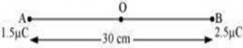
Magnitude of charge located at A, q1 =
Magnitude of charge located at B, q2 =
Distance between the two charges, d = 30 cm = 0.3 m
- Let V1 and E1 are the electric potential and electric field respectively at O.
V1 = Potential due to charge at A + Potential due to charge at B
Where,
= Permittivity of free space
E1 = Electric field due to q2 - Electric field due to q1
Therefore, the potential at mid-point is and the electric field at mid-point is . The field is directed from the larger charge to the smaller charge.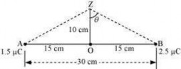
- Consider a point Z such that normal distance OZ = 10 cm = 0.1 m, as shown in the following figure.
V2 and E2 are the electric potential and electric field respectively at Z. It can be observed from the figure that distance,
BZ=AZ=
V2= Electric potential due to A + Electric Potential due to B
Electric field due to q at Z,
This field acts along AZ
Electric field due to q2 at Z,
The resultant field intensity at Z,
Where, is the angle,
From the figure, we obtain
Therefore, the potential at a point 10 cm (perpendicular to the mid-point) is and electric field is .
15: A spherical conducting shell of inner radius r1 and outer radius r2 has a charge Q
- A charge q is placed at the centre of the shell. What is the surface charge density on the inner and outer surfaces of the shell?
- Is the electric field inside a cavity (with no charge) zero, even if the shell is not spherical, but has any irregular shape? Explain.
Ans:
- Charge placed at the centre of a shell is +q. Hence, a charge of magnitude –q will be induced to the inner surface of the shell and a charge of +q is induced on the outer surface of the shell.
The total charge on the inner surface of the shell is –q.
Surface charge density at the inner surface of the shell is given by the relation,
A charge of +q is induced on the outer surface of the shell. A charge of magnitude Q is placed on the outer surface of the shell. Therefore, total charge on the outer surface of the shell is Q + q. Surface charge density at the outer surface of the shell, - Yes, the electric field intensity inside a cavity is zero, even if the shell is not spherical and has any irregular shape. The net charge on the inner surface enclosing the cavity is zero, since a charge placed in the cavity induces an equal and opposite charge on the inner surface, irrespective of the size or shape of the surface. By Gauss theorem, the electric field inside a cavity is zero.
16:
- Show that the normal component of electrostatic field has a discontinuity from one side of a charged surface to another given by Where is a unit vector normal to the surface at a point and is the surface charge density at that point. (The direction of is from side 1 to side 2). Hence show that just outside a conductor, the electric field is
- Show that the tangential component of electrostatic field is continuous from one side of a charged surface to another. [Hint: For (a), use Gauss’s law. For, (b) use the fact that work done by electrostatic field on a closed loop is zero.]
Ans:
- Electric field on one side of a charged body is E1 and electric field on the other side of the same body is E2.
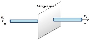
If infinite plane charged body has a uniform thickness, then electric field due to one surface of the charged body is given by,
Where,
= Unit vector normal to the surface at a point
= Surface charge density at that point.
Electric field due to the other surface of the charged body,
Electric field at any point due to the two surfaces,
Since E1 and E2 act in opposite directions, there is a discontinuity at the sheet of charge.
Since inside a closed conductor, ,
Therefore, the electric field just outside the conductor is . - Work done in an electric field over a closed path of length l is given by,
The tangential components of the vectors E1 and E2 are and respectively.
When a charged particle is moved from one point to the other on a closed loop, the work done by the electrostatic field is zero. - Therefore,
Hence, the tangential component of electrostatic field is continuous from one side of a charged surface to the other.
17: A long charged cylinder of linear charged density is surrounded by a hollow co-axial conducting cylinder. What is the electric field in the space between the two cylinders?
Ans: Charge density of the long charged cylinder of length L and radius r is .
Another cylinder of same length surrounds the pervious cylinder. The radius of this cylinder is R.
Let E be the electric field produced in the space between the two cylinders.
Electric flux through the Gaussian surface is given by Gauss's theorem as,
Where, d = Distance of a point from the common axis of the cylinders Let q be the total charge on the cylinder.
It can be written as
Where,
q = Charge on the inner sphere of the outer cylinder
= Permittivity of free space
Therefore, the electric field in the space between the two cylinders is .
18: In a hydrogen atom, the electron and proton are bound at a distance of about 0.53 .
- Estimate the potential energy of the system in eV, taking the zero of the potential energy at infinite separation of the electron from proton.
- What is the minimum work required to free the electron, given that its kinetic energy in the orbit is half the magnitude of potential energy obtained in (a)?
- What are the answers to (a) and (b) above if the zero of potential energy is taken at 1.06 separation?
Ans: The distance between electron-proton of a hydrogen atom, d = 0.53A
Charge on an electron, q1
Charge on a proton, q2
- Potential at infinity is zero.
Potential energy of the system, PE = Potential energy at infinity - Potential energy at distance d
Where,
is the permittivity of free space
Potential energy
Since
Potential energy
= -27.2eV
Therefore, the potential energy of the system is -27.2eV. - Kinetic energy is half of the magnitude of potential energy.
Kinetic energy
Total energy = 13.6-27.2 = -13.6 eV
Therefore, the minimum work required to free the electron is 13.6 eV. - When zero of potential energy is taken, d1 = 1.06A
Potential energy of the system = Potential energy at d1 - Potential energy at d
= 13.58 eV - 27.2 eV
= 13.6 eV
19: If one of the two electrons of a H2 molecule is removed, we get a hydrogen molecular ion . In the ground state of an , the two protons are separated by roughly 1.5 , and the electron is roughly 1 from each proton. Determine the potential energy of the system. Specify your choice of the zero of potential energy.
Ans: The system of two protons and one electron is represented in the given figure.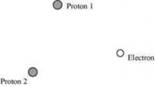
Charge on proton 1,
Charge on proton 2,
Charge on electron,
Distance between protons 1 and 2, d1 =
Distance between proton 1 and electron, d2
Distance between proton 2 and electron, d3 =
The potential energy at infinity is zero.
Potential energy for system of 3 charges is given by
Substituting
= -19.2eV
Therefore, the potential energy of the system is -19.2eV.
20: Two charged conducting spheres of radii a and b are connected to each other by a wire. What is the ratio of electric fields at the surfaces of the two spheres? Use the result obtained to explain why charge density on the sharp and pointed ends of a conductor is higher than on its flatter portions.
Ans: Let a be the radius of a sphere A, QA be the charge on the sphere, and CA be the capacitance of the sphere. Let b be the radius of a sphere B, QB be the charge on the sphere, and CB be the capacitance of the sphere. Since the two spheres are connected with a wire, their potential (V) will become equal.
Let EAbe the electric field of sphere A and EB be the electric field of sphere B. Therefore, their ratio,
.........(1)
However
And
........(2)
Putting the value of (2) in (1), we obtain
Therefore, the ratio of electric fields at the surface is .
Since the electric field intensity due to a conductor is directly proportional to its charge density,
The charge density of a conductor is inversely proportional to its radius. Smaller the radius, greater is the charge density of the surface. Sharp points on a conductor have small radii and hence the charge density at such points is greater than the charge density on flatter parts of the surface.
21: Two charges -q and +q are located at points ( 0,0,-a) and ( 0,0,a) respectively.
- What is the electrostatic potential at the points (0,0,z) and (x,y,0)?
- Obtain the dependence of potential on the distance r of a point from the origin when r/a >> 1.
- How much work is done in moving a small test charge from the point (5, 0, 0) to (-7,0,0) along the x-axis? Does the answer change if the path of the test charge between the same points is not along the x-axis?
Ans:
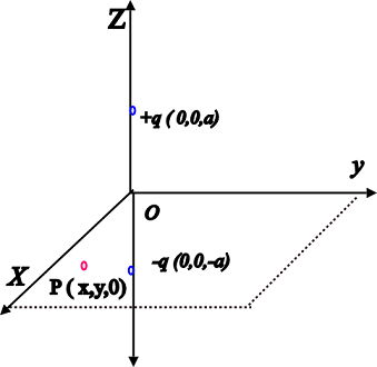
Charge - q is located at (0, 0, -a) and charge + q is located at (0, 0, a). Hence, they form a dipole. Point (0, 0, z) is on the axis of this dipole and point (x, y, 0) is normal to the axis of the dipole. Hence, electrostatic potential at point (x, y, 0) is zero.
The point P lies at a point where z>a
Electrostatic potential at point (0, 0, z) is given by,
Where,
= Permittivity of free space
p = Dipole moment of the system of two charges = 2qa
If z<a,
If the point lies at a distance z closer to -q, the potential is same as- Distance r is much greater than half of the distance between the two charges.
Let z = r in the equation
For r >> a,
Hence, the potential (V) at a distance r is inversely proportional to square of the distance
i.e., - Zero
A test charge is moved from point (5, 0, 0) to point (7, 0, 0) along the x-axis. Electrostatic potential (V1) at point (5, 0, 0) is given by,
= 0
Electrostatic potential, V2, at point ( 7, 0, 0) is given by,
= 0
Hence, no work is done in moving a small test charge from point (5, 0, 0) to point (7, 0, 0) along the x-axis.
The answer does not change if the path of the test is not along the x-axis because work done by the electrostatic field in moving a test charge between the two points is independent of the path connecting the two points.
22: Figure shows a charge array known as an electric quadrupole. For a point on the axis of the quadrupole, obtain the dependence of potential on r for r/a >> 1, and contrast your results with that due to an electric dipole, and an electric monopole (i.e., a single charge).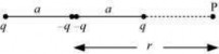
Ans: Four charges of same magnitude are placed at points X, Y, Y, and Z respectively, as shown in the following figure.
A point is located at P, which is r distance away from point Y. The system of charges forms an electric quadrupole.
It can be considered that the system of the electric quadrupole has three charges.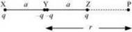
Charge +q placed at point X
Charge -2q placed at point Y
Charge +q placed at point Z
XY = YZ = a
YP = r
PX = r + a
PZ = r - a
Electrostatic potential caused by the system of three charges at point P is given by,
Since ,
is taken as negligible.
It can be inferred that potential,
However, it is known that for a dipole,
And, for a monopole,.
23: An electrical technician requires a capacitance of 2µF in a circuit across a potential difference of 1 kV. A large number of 1 µF capacitors are available to him each of which can withstand a potential difference of not more than 400 V. Suggest a possible arrangement that requires the minimum number of capacitors.
Ans: Total required capacitance, C =2µF Potential difference, V = 1 kV = 1000 V Capacitance of each capacitor,C1 = 1 µF
Each capacitor can withstand a potential difference, V1 = 400 V
Let n capacitors be connected in series and these series circuits are connected in parallel forming m rows . The potential difference across each row must be 1000 V and potential difference across each capacitor must be 400 V. Hence, number of capacitors in each row is given as
Since the number of capacitors cannot be in fractions, therefore, there are 3 capacitors in each row.
Capacitance of each row
If m such capacitors are connected in parallel, the equivalent capacitance of the combination is the needed value of capacitance of 2µF. Therefore,
Let there are 6 rows, each having 3 capacitors, which are connected in parallel. Hence, the total number of capacitors required is 6 3 = 18
24: What is the area of the plates of a 2 F parallel plate capacitor, given that the separation between the plates is 0.5 cm? [You will realize from your answer why ordinary capacitors are in the range of or less. However, electrolytic capacitors do have a much larger capacitance (0.1 F) because of very minute separation between the conductors.]
Ans: Capacitance of a parallel capacitor, V = 2 F
Distance between the two plates, d = 0.5 cm = Capacitance of a parallel plate capacitor is given by the relation,
Where,
= Permittivity of free space
= 1130km2
Hence, the area of the plates is too large. To avoid this situation, the capacitance is taken in the range of micro Farads.
25: Obtain the equivalent capacitance of the network in Fig. 2.35. For a 300 V supply, determine the charge and voltage across each capacitor.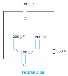
Ans: Capacitance of capacitor C1 is 100 pF.
Capacitance of capacitor C2 is 200 pF.
Capacitance of capacitor C3 is 200 pF.
Capacitance of capacitor C4 is 100 pF.
Supply potential, V = 300 V
The circuit is redrawn as below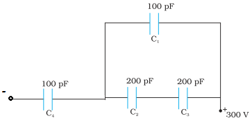
Capacitors C2 and C3 are connected in series. Let their equivalent capacitance be C'
C1 = 100pF
Capacitors C1and C' are in parallel. Let their equivalent capacitance be Cn
= 100 + 100 = 200pF
Cn and C4are connected in series. Let their equivalent capacitance be C.
Hence, the equivalent capacitance of the circuit is
The total charge stored in the network is
The charge on C4 is
The potential difference across C4 is
The potential difference across the parallel combination is V1= 300 - 200 =100 V
The charge on C1 is
Since C2= C3, the potential difference across the capacitors are equal.
The charges stored are also equal ,
.
26: The plates of a parallel plate capacitor have an area of 90 each and are separated by 2.5 mm. The capacitor is charged by connecting it to a 400 V supply.
- How much electrostatic energy is stored by the capacitor?
- View this energy as stored in the electrostatic field between the plates, and obtain the energy per unit volume u. Hence arrive at a relation between u and the magnitude of electric field E between the plates.
Ans: Area of the plates of a parallel plate capacitor, A = 90 cm2
Distance between the plates, d = 2.5 mm
Potential difference across the plates, V = 400 V
- Capacitance of the capacitor is given by the relation,
Electrostatic energy stored in the capacitor is given by the relation,
Where,
= Permittivity of free space =
Hence, the electrostatic energy stored by the capacitor is - Volume of the given capacitor,
Energy stored in the capacitor per unit volume is given by
Where,
Since the electric field intensity
.
27: A 4 capacitor is charged by a 200 V supply. It is then disconnected from the supply, and is connected to another uncharged 2 capacitor. How much electrostatic energy of the first capacitor is lost in the form of heat and electromagnetic radiation?
Ans: Capacitance of a charged capacitor, Supply voltage, V1 = 200 V
Electrostatic energy stored in C1 is given by,
Capacitance of an uncharged capacitor,
When C2 is connected to the circuit, the potential acquired by it is V2.
According to the conservation of charge, initial charge on capacitor C1 is equal to the final charge on capacitors, C1 and C2.
Electrostatic energy for the combination of two capacitors is given by,
Hence, amount of electrostatic energy lost by capacitor .
28: Show that the force on each plate of a parallel plate capacitor has a magnitude equal to (1/2 ) QE, where Q is the charge on the capacitor, and E is the magnitude of electric field between the plates. Explain the origin of the factor 1/2.
Ans: Let F be the force applied to separate the plates of a parallel plate capacitor by a distance of . Hence, work done by the force to do so
As a result, the potential energy of the capacitor increases by an amount .
Where,
u = Energy density
A = Area of each plate
d = Distance between the plates
V = Potential difference across the plates
The work done will be equal to the increase in the potential energy i.e.,
Electric Field intensity is given by,
However, capacitance,
Charge on the capacitor is given by,
Q = CV
The physical origin of the factor, , in the force formula lies in the fact that just outside the conductor, field is E and inside it is zero. Hence, it is the average value, , of the field that contributes to the force.
29: A spherical capacitor consists of two concentric spherical conductors, held in position by suitable insulating supports . Show that the capacitance of a spherical capacitor is given by where r1 and r2 are the radii of outer and inner spheres, respectively.
Ans: Radius of the outer shell = r1
Radius of the inner shell = r2
The inner surface of the outer shell has charge +Q.
The outer surface of the inner shell has induced charge -Q. Potential difference between the two shells is given by,
Where, = Permittivity of free space
Capacitance of the given system is given by,
Hence, proved.
30: A spherical capacitor has an inner sphere of radius 12 cm and an outer sphere of radius 13 cm. The outer sphere is earthed and the inner sphere is given a charge of 2.5 µC. The space between the concentric spheres is filled with a liquid of dielectric constant 32.
- Determine the capacitance of the capacitor.
- What is the potential of the inner sphere?
- Compare the capacitance of this capacitor with that of an isolated sphere of radius 12 cm. Explain why the latter is much smaller.
Ans: Radius of the inner sphere, r2 = 12 cm = 0.12 m Radius of the outer sphere, r1 = 13 cm = 0.13 m Charge on the inner sphere,
Dielectric constant of a liquid,
(a) Capacitance of the capacitor is given by the relatioon,
Where,
= Permittivity of free space =
Hence, the capacitance of the capacitor is approximately .
- Potential of the inner sphere is given by,
Hence, the potential of the inner sphere is . - Radius of an isolated sphere,
- Capacitance of the sphere is given by the relation,
The capacitance of the isolated sphere is less in comparison to the concentric spheres. This is because the outer sphere of the concentric spheres is earthed. Hence, the potential difference is less and the capacitance is more than the isolated sphere.
31: Answer carefully:
- Two large conducting spheres carrying charges Q1 and Q2 are brought close to each other. Is the magnitude of electrostatic force between them exactly given by , where r is the distance between their centres?
- If Columb’s law involved 1/r3 dependence (instead of 1/r2), would Gauss’s law be still true?
- A small test charge is released at rest at a point in an electrostatic field configuration. Will it travel along the field line passing through that point?
- What is the work done by the field of a nucleus in a complete circular orbit of the electron? What if the orbit is elliptical?
- We know that electric field is discontinuous across the surface of a charged conductor. Is electric potential also discontinuous there?
- What meaning would you give to the capacitance of a single conductor?
- Guess a possible reason why water has a much greater dielectric constant (= 80) than say, mica (= 6).
Ans:
- Coulomb's law is valid for force between two point charges. The force between two conducting spheres is not exactly given by the expression , because as the spheres are brought closer, the charge distribution becomes non-uniform and they no longer behave as point charges.
- Gauss law involves integration over a surface for the determination of flux.
If Coulomb’s law involved 1/r3 dependence, instead of1/r2, Gauss law will not hold true since the flux would then depend on r too. - Not necessarily; If a small test charge is released at rest at a point in an electrostatic field configuration, then it will travel along the field lines passing through the point, only if the field lines are straight. This is because the field lines give the direction of acceleration and not of velocity.
- Whenever the electron completes an orbit, either circular or elliptical, the work done by the field of a nucleus is zero since the electrostatic field is a conservative field.
- No Electric field is discontinuous across the surface of a charged conductor. However, an electric potential is continuous and has a constant value.
- The capacitance of a single conductor is considered as a parallel plate capacitor with one of its two plates at infinity.
- Water is assymetrical molecule when compared to mica. Since it has a permanent dipole moment, it has a greater dielectric constant than mica.
32: A cylindrical capacitor has two co-axial cylinders of length 15 cm and radii 1.5 cm and1.4 cm. The outer cylinder is earthed and the inner cylinder is given a charge of 3.5 . Determine the capacitance of the system and the potential of the inner cylinder. Neglect end effects (i.e., bending of field lines at the ends).
Ans: Length of a co-axial cylinder, l = 15 cm = 0.15 m
Radius of outer cylinder, r1 = 1.5 cm = 0.015 m
Radius of inner cylinder, r2 = 1.4 cm = 0.014 m
Charge on the inner cylinder, q = 3.5
Capacitance of a co-axil cylinder of radii r1 and r2 is given by the relation,
Where,
= Permittivity of free space =
Potential difference of the inner cylinder is given by,
.
33: A parallel plate capacitor is to be designed with a voltage rating 1 kV, using a material of dielectric constant 3 and dielectric strength about 107Vm-1. (Dielectric strength is the maximum electric field a material can tolerate without breakdown, i.e., without starting to conduct electricity through partial ionisation.) For safety, we should like the field never to exceed, say 10% of the dielectric strength. What minimum area of the plates is required to have a capacitance of 50 pF?
Ans: Potential rating of a parallel plate capacitor, V = 1 kV = 1000 V
Dielectric constant of a material, =3 Dielectric strength = 107 V/m
For safety, the field intensity never exceeds 10% of the dielectric strength. Hence, electric field intensity, E = 10% of 107 = 106V/m
Capacitance of the parallel plate capacitor, C = 50 pF
Distance between the plates is given by,
Capacitance is given by the relation,
Where, A = Area of each plate
= Permittivity of free space
Hence, the area of each plate is about 19 cm2.
34: Describe schematically the equipotential surfaces corresponding to
1. a constant electric field in the z-direction,
2. a field that uniformly increases in magnitude but remains in a constant (say, z) direction,
3. a single positive charge at the origin, and
4. a uniform grid consisting of long equally spaced parallel charged wires in a plane.
Ans: 1. Equidistant planes parallel to the x-y plane are the equipotential surfaces.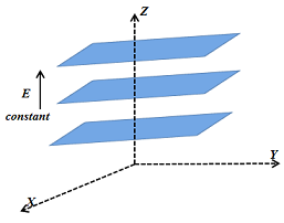
2. Planes parallel to the x-y plane are the equipotential surfaces with the exception that when the planes get closer, the field increases.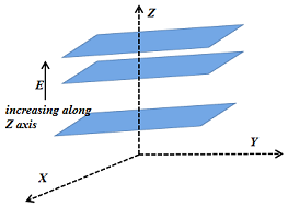
3. Concentric spheres centered at the origin are equipotential surfaces.
4. A periodically varying shape near the given grid is the equipotential surface. This shape gradually reaches the shape of planes parallel to the grid at a larger distance.
35: In a Van de Graaff type generator a spherical metal shell is to be a electrode. The dielectric strength of the gas surrounding the electrode is . What is the minimum radius of the spherical shell required? (You will learn from this exercise why one cannot build an electrostatic generator using a very small shell which requires a small charge to acquire a high potential.)
Ans: Potential difference, V =
Dielectric strength of the surrounding gas =
Electric field intensity, E = Dielectric strength =
Minimum radius of the spherical shell required for the purpose is given by,
Hence, the minimum radius of the spherical shell required is 30 cm.
36: A small sphere of radius r1 and charge q1 is enclosed by a spherical shell of radius r2 and charge q2. Show that if q1 is positive, charge will necessarily flow from the sphere to the shell (when the two are connected by a wire) no matter what the charge q2 on the shell is.
Ans: Consider a sphere of radius r1 carrying a charge q1 placed inside a spherical shell of radius r2 carrying a charge q2.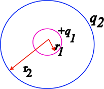
The total potential of the outer sphere VO = potential due to the charge q2 on its surface + potential due to charge q1on the inner sphere.
The potential on the inner sphere is Vi = potential due to the charge q1on its surface and the potential due to charge q2 on the outer sphere. The potential due to the charge on the outer sphere is constant through out the volume of the hollow spherical shell. Therefore,
The potential difference between the inner and the outer conductors is given by
since r1<r2, Vi - VO will be positive if q1 is positive. The charge therefore will always flow from the inner sphere to the outer sphere if both are connected , irrespective of the value of the charge on the outer sphere.
37: Answer the following:
- The top of the atmosphere is at about 400 kV with respect to the surface of the earth, corresponding to an electric field that decreases with altitude. Near the surface of the earth, the field is about 100V/m. Why then do we not get an electric shock as we step out of our house into the open? (Assume the house to be a steel cage so there is no field inside!)
- A man fixes outside his house one evening a two metre high insulating slab carrying on its top a large aluminium sheet of area 1m2. Will he get an electric shock if he touches the metal sheet next morning?
- The discharging current in the atmosphere due to the small conductivity of air is known to be 1800 A on an average over the globe. Why then does the atmosphere not discharge itself completely in due course and become electrically neutral? In other words, what keeps the atmosphere charged?
- What are the forms of energy into which the electrical energy of the atmosphere is dissipated during a lightning? (Hint: The earth has an electric field of about 100Vm-1 at its surface in the downward direction, corresponding to a surface charge density = -10-9C m-2 . Due to the slight conductivity of the atmosphere up to about 50 km (beyond which it is good conductor), about +1800C is pumped every second into the earth as a whole. The earth, however, does not get discharged since thunderstorms and lightning occurring continually all over the globe pump an equal amount of negative charge on the earth.)
Ans:
- We do not get an electric shock as we step out of our house because the original equipotential surfaces of open air changes, keeping our body and the ground at the same potential. This is because our body is a good conductor.
- Yes, the man will get an electric shock if he touches the metal slab next morning. The steady discharging current in the atmosphere charges up the aluminum sheet. As a result, its voltage rises gradually. The raise in the voltage depends on the capacitance of the capacitor formed by the aluminium slab and the ground.
- The occurrence of thunderstorms and lightning charges the atmosphere continuously. Hence, even with the presence of discharging current of 1800 A, the atmosphere is not discharged completely. The two opposing currents are in equilibrium and the atmosphere remains electrically neutral.
- During lightning and thunderstorm, light energy, heat energy, and sound energy are dissipated in the atmosphere.